I recently purchased an Orange Pi Zero3 so that I’d have a platform for IoT-based projects I have planned. My evaluation process at the time of purchase was fairly simple:
- this board is pretty powerful
- this board can connect to the internet
- this board is cheap-ish (~30$)
Once it arrived I began to realize that my evaluation process was…slightly flawed.
The first sign of trouble came when I searched for an OS that would run on the board. Instead of a list of options and tutorials, I found issues with the proprietary OSes provided by Orange Pi including a reddit thread describing some security concerns and an Ars Technica report describing security issues with kernel releases for/by Allwinner (the system-on-chip used on the Orange Pi).
None of the existing options seemed appealing, so I figured I’d just make a bare-minimum Linux image myself.
Making a custom Linux OS for the Zero3
This is all possible due to the mainline support for the Zero3 in both u-boot and the mainline Linux kernel. While the Sunxi-Linux wiki has a very thorough, detailed guide, I found it quite difficult to navigate when I was first getting started. This guide is meant to get you from zero to command line prompt as quickly as possible.
Part 1 will cover the required tools, our development environment, and creating a bootloader that we can load onto our micro-SD card. Part 2 will deal with the compilation of our OS’s parts - the kernel, device tree, rootfs, and modules.
What you need
- USB-to-TTL adapter
- Micro-SD card
- Micro-SD card reader (I used a usb reader)
- Orange Pi Zero3
- Power supply (USB-C Adapter)
- Linux environment (I used a VM running Ubuntu Server)
- Toolchain - creating a boot image requires quite a few packages. Running the following command should install the majority of the packages you will need:
sudo apt-get -y install swig python3-dev build-essential device-tree-compiler git screen bison flex python3-setuptools libssl-dev dosfstools libncurses-dev bc rsync
I have tried to make this an exhaustive list of necessary packages, but your mileage may vary.
Finally - this guide assumes you already have an Aarch64 Linux environment set up and you have familiarity with the Linux command line.
Work Environment
To start, we’ll need a place to store the Linux repo and U-Boot repo. I created opi-image/ in my home directory, but you can call it whatever you want.
In order to create our boot image, we’ll need a bootloader, kernel, device tree, and root filesystem. To make these components, we’ll need the necessary repositories.
In opi-image/, we can clone Linus’s repo, the u-boot repo, the ARM trusted firmware repo, and the linux-firmware repo:
git clone git://git.kernel.org/pub/scm/linux/kernel/git/torvalds/linux.git

git clone git://git.denx.de/u-boot.git

git clone https://github.com/ARM-software/arm-trusted-firmware.git

git clone git://git.kernel.org/pub/scm/linux/kernel/git/firmware/linux-firmware.git linux-firmware
After, your project structure should look like this:
opi-image/
| - - linux/
| - - u-boot/
| - - arm-trusted-firmware/
| - - linux-firmware/
Trusted Firmware-A
What did I just clone?
TF-A is responsible for initializing our board’s hardware in a secure manner. In our case, the H616/H618’s architecutre is ARMv8, so TF-A uses an Exception Level 3 (EL3) firmware layer to securely set up a space for u-boot to run at a lower Exception Level.
My understanding of this process is still very high level, so if you’re curious about the work being done by TF-A, the documentation is thorough and has a specific entry for the Allwinner H616 (and other Allwinner chips).
Step 1
Navigate into arm-trusted-firmware/ and run the following command:
make CROSS_COMPILE=aarch64-linux-gnu- PLAT=sun50i_h616 DEBUG=1 bl31
The arguments in this make command are largely self-explanatory with the exception of bl31.
Per the TF-A documentation, bl31 actually stands for boot loader stage 3-1. bl31 is responsible for, among other things, “passing control to a normal world BL image”. Frankly, I had a hard time digging up information about what this actually meant. Based on what I found, my current best guess is that, in our case, we are using boot loader stage 3-1 to pass control from our TF-A firmware over to the actual u-boot image that we generate in later steps.
Step 2
Once complete, navigate into u-boot/ and run the following command:
make CROSS_COMPILE=aarch64-linux-gnu- BL31=../arm-trusted-firmware/build/sun50i_h616/debug/bl31.bin orangepi_zero3_defconfig
You’ll need to adjust the BL31=[PATH] parameter if you adopted a different project structure from mine. Once complete, you can make the u-boot .bin file:
make CROSS_COMPILE=aarch64-linux-gnu- BL31=../arm-trusted-firmware/build/sun50i_h616/debug/bl31.bin
The ouput of this command should include a file called u-boot-sunxi-with-spl.bin.
Again, you may be wondering “why not just u-boot.bin?”. The reason has to do with our board’s boot flow. It’s easy to think of the process as being “power on -> load u-boot”, but there is quite a bit more happening on our ARMv8 board. In our case, the process looks more like this:
boot ROM -> TF-A with BL31 -> Secondary Program Loader (SPL) -> U-boot
Each step prepares the hardware and hands over control to the subsequent program. This is all a little low-level for our purposes (the .bin file we generated handles the nitty-gritty), but it’s nice to know what’s happening under the hood.
Preparing our SDCard
After connecting the SDcard to our linux system we need to identify it on our system. Because I used a USB adapter, my micro-SD card was identified as sdX (usually sda). You can run the lsblk command to see what block devices are available on your system.
Step 1
Once you have identified your micro-SD card, we should wipe the first section of it to ensure that any existing partition table is removed:
sudo dd if=/dev/zero of=/dev/sdX bs=1M count=1
The dd command is used for copying data from one file to another. In the above command, we’re copying a blocksize of 1 Megabyte (bs=1M) from /dev/zero (input file) to /dev/sdX (output file) one time (count=1).
Step 2
Once that is complete, we can write our bootloader to it:
sudo dd if=u-boot-sunxi-with-spl.bin of=/dev/sdX bs=1024 seek=8
This time we use the dd command to copy the contents of our u-boot .bin file onto our micro-SD card. The ‘count=’ parameter isn’t set, meaning the copying will continue until the input file is fully copied.
The Seek argument is used as an offset, telling the dd command how many blocks to ‘skip’ from the start of the output file before writing the input file data. Because we’ve set the blocksize to 1024 bytes, our dd command will begin copying our .bin file 8 * 1024 bytes into our micro-SD card.
Though the u-boot documentation is light on this issue, the purpose of the ‘gap’ (8 blocks) likely relates to the leaving space for our memory’s partition table.
Step 3
Before ejecting our micro-SD card and testing our bootloader, we should partition our SD Card into boot and root partitions.
Run the following command, updating the reference to your micro-SD card as necessary:
sudo blockdev --rereadpt /dev/sdX
cat <<EOT | sudo sfdisk /dev/sdX
1M,64M,c
,,L
EOT
A lot is happening in this command. First - blockdev --rereadpt is telling our workspace kernel to re-read the block device located at /dev/sdX. Because subsequent commands will be changing the partition table on the block device, we want our workspace to have a current snapshot of the block device’s partitions.
The sfdisk command is used for manipulating disk partitions. The cat<<EOT | chunk feeds the subsequent lines as input into the sfdisk command until an EOT is entered.
1M,16M,c tells sfdisk to create a partition starting at 1 megabyte and having a total size of 64 megabytes. The third value is a hexadecimal representation of the partition’s file type. In our case, 0xC represents Fat32 (LBA).
,,L tells sfdisk to use the remainder of the disk to create a second partition formatted as a Linux Filesystem. Note that, here, the L is not a number value but instead an alias for ’linux’.
Step 4
Now that our micro-SD card has been partitioned properly, we can format the partitions using the mkfs tool. Run the following commands:
sudo mkfs.vfat /dev/sdaX1
sudo mkfs.ext4 /dev/sdaX2
mkfs stands for ‘make filesystem’. In the above commands, we’re telling mkfs to format our first partition as VFat, and our second as Ext4.
At first glance Step 3 and Step 4 may seem to be redundant, but it comes down to the differences between sfdisk and mkfs.
Sfdisk is partitioning the block device - it splits our /dev/sdX into /dev/sdX1, /dev/sdX2, etc. Mkfs formats these partitions, creating filesystem structures that allow us to store directories, files, and so on.
Testing
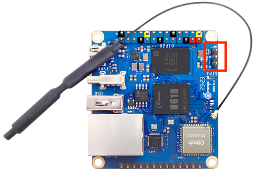
Eject your micro-SD card from your workstation and insert it into your Zero3. Connect your usb-to-ttl adapter to your work station and the TTL debug pins on the Zero3 (shown below). In your terminal, open a screen session at your USB-to-TTL adapter’s address. I used a baudrate of 115200 for my connection, but that may depend on your u-boot version/settings.
Power on your Zero3 and you should see u-boot’s output!