The Orange Pi Zero3 includes 13 GPIOs dedicated to an expansion shield (pictured below).
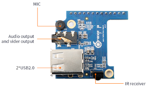
However, the first time I tried using one of the USB ports on it I got no response at all from the system. This post outlines the steps necessary to enable the 13-pin expansion shield on the Zero3.
USB2, USB3, and CIR on the Allwinner H616/H618
We first need to figure out how the 13 expansion GPIOs are connected to our SOC. In order to figure out how to get it working I started by looking up the Allwinner H618’s datasheet. I was unable to find the datasheet for the H618 but did manage to locate a copy of the H616 datasheet. The only difference between the two SOCs that I have found any reference to is the size of the L2 Cache, so it should have the information we need about the H618.
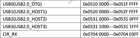
Section 2.2.10.1 of the datasheet lists 4 USB peripherals on the H616/618, which matches with the one onboard Type-A USB port, the onboard Type-C USB port, and the two Type-A USB ports on the expansion shield. Section 2.2.10.6 describes the CIR sensor that is also present on the expansion shield. Section 3 of the data sheet set out the memory-mapped addresses for the USB ports as well:
Comparing this information to the Zero3’s Device Tree
Device Tree Source and Binary
The Device Tree is an XML-like filetype that allows the kernel/OS to dynamically understand the hardware and peripherals present on a system. Because this information does not need to be hardcoded, it is very useful for embedded systems where the hardware may vary greatly between models and devices - the OS/Kernel does not need to be updated/revised for each device. The same kernel can be released for multiple systems, with each one able to refer to the device tree for the system’s hardware information.
Viewing the Device Tree
We can use the device-tree-compiler tool to work with device tree files, including:
- Device Tree Source (
.dts) files: the human-readable version of a device tree file - Device Tree Binary (
.dtb) files: the binary representation of the device tree - Device Tree Binary Overlay (
.dtbo) files: the binary representation of an overlay file, which is intended to modify an existing
On my system, the .dtb (device tree binary file) is stored in the /boot directory. The following commands allow us to see a human-readable version of it:
sudo apt-get install device-tree-compiler
dtc -I dtb -O dts -o - /boot/device_tree.dtb
The first command installs the tool. The second command tells the tool that our input file format (-I) is a .dtb file, the output file format (-O) should be a .dts file, and the output file (-o) should be stdout. The last parameter is the location of our input .dtb file.
There’s quite a bit of output when running this command, but parsing through it we can see that the USB2 and USB3 devices are present already in our device tree (compare the @VALUE in the name of each node to the memory-mapped address from the H616/H618 datasheet to confirm):
/ { ...
    soc {
        ...
		usb@5310000 {
			...
			status = "disabled";
		};

		usb@5310400 {
			...
			status = "disabled";
		};

		usb@5311000 {
			...
			status = "disabled";
		};

		usb@5311400 {
			...
			status = "disabled";
		};
        ...
        ir@7040000 {
            ...
			status = "disabled";
		};
    ...
    };
    ...
};
Note that I’ve edited out quite a bit of information from each node, but we can see that the additional USB ports as well as our IR sensor on the expansion shield are already present in our device tree, but their status is set to disabled. So…how do we enable them?
Creating a device tree overlay
We can amend our system’s device tree by creating what is called a device tree overlay file (.dtbo). As the name suggests, we can add (or in our case, overwrite) the contents of the device tree by overlaying new nodes and/or information. Because the peripherals we want to use are already in the device tree, all we need to do is enable them. For example:
/dts-v1/;
/plugin/;

/ {
    fragment@0 {
        target-path = "/";
        __overlay__ {
            soc {
                usb@5310000 {
                    status = "okay";
                };
                ...
            };
        };
    };
};
You can find a copy of the .dts file I used here. In your working directory, can compile the source file into a binary file with the following command:
dtc -@ -I dts -O dtb -o expansion-board-overlay.dtbo expansion-board-overlay.dts
You may see some warnings when running this command, for example:
expansion-board-overlay.dts:9.29-11.19: Warning (unit_address_vs_reg): /fragment@0/__overlay__/soc/usb@5310000: node has a unit name, but no reg or ranges property
expansion-board-overlay.dts:13.29-15.19: Warning (unit_address_vs_reg): /fragment@0/__overlay__/soc/usb@5310400: node has a unit name, but no reg or ranges property
It appears that this warning has to do with issues within the dtc tool relating to the current fragment/overlay syntax. If you want, you can surpress them by including a supression flag:
dtc -W no-unit_address_vs_reg -@ -I dts -O dtb -o expansion-board-overlay.dtbo expansion-board-overlay.dts
Now that we have a compiled overlay, we can copy it into the RootFS boot directory:
sudo cp expansion-board-overlay.dtbo /boot/
Now we need to implement the new overlay in our system’s boot process.
Revising the boot script
The barebones script for booting the Orange Pi Zero3, below, sets the location of the root directory, loads the device tree binary, loads the kernel image, and boots.
setenv bootargs root=/dev/mmcblk0p2
load mmc 0:1 $kernel_addr_r Image
load mmc 0:1 $fdt_addr_r device_tree.dtb
booti $kernel_addr_r - $fdt_addr_r
We need to update the script to implement the device tree overlay. I made use of pre-defined variables to write the script. When I run printenv in the bootloader prompt (after interrupting the boot process), I can see the following variables:
fdt_addr_r=0x4FA00000
fdtoverlay_addr_r=0x4FE00000
kernel_addr_r=0x40080000
I can use the fdtoverlay_addr_r variable to load in the overlay file. Starting from scratch in a new file (I called mine boot.cmd), the first few lines are similar to our original script:
setenv bootargs root=/dev/mmcblk0p2
load mmc 0:1 $kernel_addr_r Image
load mmc 0:1 $fdt_addr_r device_tree.dtb
load mmc 0:1 $fdtoverlay_addr_r expansion-board-overlay.dtbo
Once the files are loaded into memory, we need to designate which file is the file device tree and resize it to accomodate the overlay file:
fdt addr $fdt_addr_r
fdt resize 8192
Finally, we need to apply the overlay to our original device tree:
fdt apply $fdtoverlay_addr_r
Then we can run the booti command as before:
booti $kernel_addr_r - $fdt_addr_r
A complete version of the script is included in the repo for this post.
Compile the revised boot script
In order to compile our .cmd file into a .scr file we’ll need the mkimage tool from u-boot. We can install it with the following command:
sudo apt-get install u-boot-tools
You can check that mkimage was successfully installed by checking its version:
user@orangepi:/# mkimage --version
mkimage version 2023.01
We can now compile our .cmd file with the following command:
mkimage -A arm -T script -C none -d boot.cmd boot.scr
The -A flag sets the architecture, the -T flag sets the file type (we want script, but the mkimage tool can be used for kernel images and other files as well), and -C sets the compression algorithm for the file.
After running this command, replace the current boot script in your system’s /boot directory with the new version and reboot your system.
Once you’ve logged back in, and assuming you’ve plugged the expansion shield into your board, you should be able to see the newly-added usb ports when running the lsusb command.
Hopefully you found this helpful. Thanks for reading!
All of the files used in this post can be found on github.